EPD understands the important challenges you face in sourcing out the design and manufacturing of your electronic product given the every changing advances in technology. Our resource area helps you keep up with the new technological terms of the industry.
Our resource area provides you with information, case studies and related resource links to help you find the information you need in designing and producing your electronic product.
Every LCD is unique in its electronic drive and connector requirements. Consequently, we faced some interesting challenges when we wanted to replace a simple LCD display and LED indicators in a client's product with a touch-screen display:
The solution was to design an RS232 (serial) touch-screen display that has a specialized PIC24 processor and dedicated software necessary to control it.
Integrating this new touch-screen would involve all facets of EPD Electronic's design and assembly abilities.
Here are the steps we took to successfully accomplish this.

We worked with the client to determine what they wanted to have the touch-screen display do and what it should look like. We then picked an appropriate touch-screen based on the size, resolution, and availability.
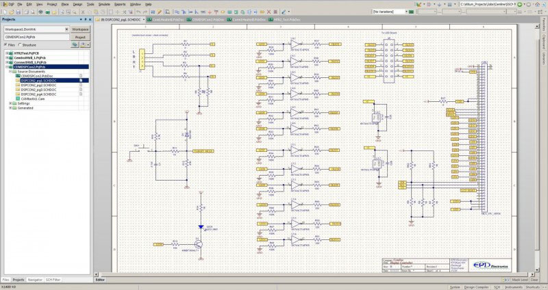
Once the display was selected, we then designed the electronics that would drive the touch-screen.
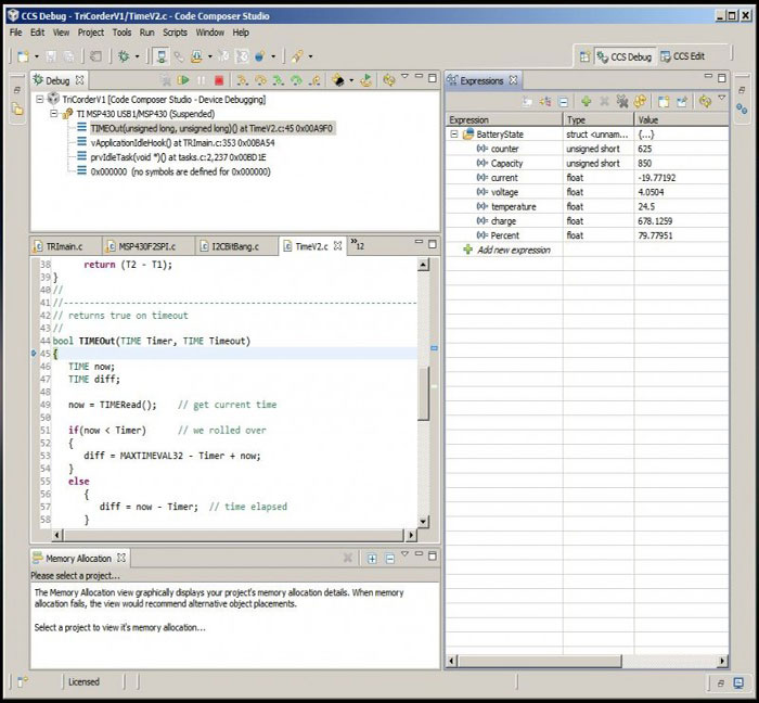
As the electronics were being designed, we also started work on the software. This is where the software commands to control the display as well as the client's graphical interface were created.
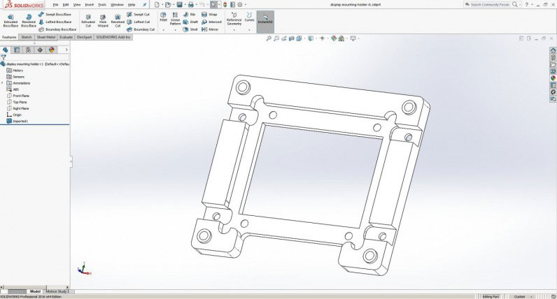
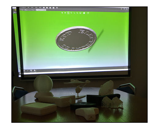
In addition to the previous steps, we also needed to create a mounting system for the display. Since the display we chose had no mounting holes of its own, we had to design in Solidworks a cradle that both held the display and the driver board to come. This cradle would then attach to the project case. Because we have two 3D printers in-house, we were able to quickly iterate plastic prototypes until we had the ideal cradle.

Once the cradle was designed, we then worked out what hardware was needed to mount everything together. Also, we needed to create a rubber gasket based on the design parameters of the cradle and the display. This was all done in Solidworks by creating a virtual assembly of the entire project.
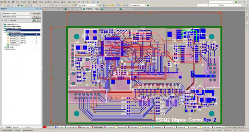
The cradle design dictated the size of the circuit board driver for the display. With that information now determined, the circuit board was designed.

The display assembly was then assembled virtually in Solidworks to verify that all the pieces fit together.
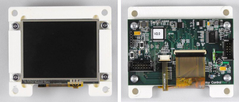
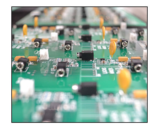
And lastly, the display was built in-house using our surface-mount machinery and skilled technicians. Once assembled, the driver board was programmed with the custom software and tested.
EIPC (European Institute of Printed Circuits) - www.eipc.org
IMAPS (International Microelectronics and Packaging Society) - www.imaps.org
IPC – Association Connecting Electronics Industries - www.ipc.org
SMTA (Surface Mount Technology Association) - www.smta.org
Circuits Assembly - www.circuitsassembly.com
Printed Circuit Design and Manufacture - www.pcdandm.com
Electronic Engineering Times - www.eetimes.com